Electrical Power System compromises of several equipment’s which are used according to the specified purpose serving different objectives in power system. Generally, power system is classified and clustered under the broad scope of generation, transmission and distribution. There are several equipment’s used for different purpose serving specified objectives in power system and such equipment’s are prone to different types of fault in their operation. In order to operate the power system smoothly, different types of protection are engaged to cope with different types of fault. But sometimes due to different reasons, the failure of protection may hamper the equipment operation and sometimes may damage the equipment as a whole. Thus, analysis of fault is very important to tackle such situations in future ensuring healthy and smooth operation of power system. In earlier days, post fault analysis was complicated since majority of protection relays was of electromagnetic type but in recent days with use of digital relays the fault analysis has became quite easier tough continuous monitoring and analysis is required.
Digital electronic relay has capability to store disturbance record (DR) within the relay which can be downloaded as COMTRADE files for better analysis. COMTRADE (Common format for Transient Data Exchange for power systems) is a file format for storing oscillography and status data related to transient power system disturbances. COMTRADE files are typically generated by Intelligent Electronic Devices (IEDs), such as an electronic protective relay, in electrical substations during power systems disturbances. These IEDs are monitoring the electrical characteristics of the power system by digitally sampling measurements of the current, voltage, power, frequency, etc. at a high speed. The COMTRADE file format has been standardized by the Power System Relaying & Controls Committee (PSRC) of the IEEE Power & Energy Society as C37.111. The most widely used version of the COMTRADE standard is C37.111-1999, but the latest version is C37.111-2014. The 1999 version of the COMTRADE standard specifies a file format that consists of multiple file types designated by the assigned file extensions of *.CFG, *.INF, *.HDR, and *.DAT. The 2014 version of the COMTRADE standard supports a variety of new features including XML encoding configuration and data, a single file type (*.CFF) that combines all the C37.111-1999 types into a single file.
In this blog, I will discuss the procedure to download DR from IEDs and will present fault analysis for fault occurrence in Power Transformer. For the analysis purpose in this blog, I shall be considering relay built by ABB such as relay model no: RET 650 for analysis of fault in transformer.
- Steps to download Disturbance Report
Every protection relay (IEDs) has their own connectivity package and software via which relay is connected with PC to fulfill different purpose. Settings, Configuration, Tripping Logic, SLD could be set in relay via this connection and at the same time disturbance report could also be downloaded. For this, you need to have PCM 600 software installed in PC and connectivity package of relay on which you are willing to work.
- Open the PCM 600 in your PC and also install connectivity package of relay from which you are willing to read or write data. For ex: RET 650 connectivity packages for transformer protection.
- Create a project in PCM 600 as displayed below and add necessary relays installed in line or transformer feeder. Once the relay is connected with PC, the blue tick sign appears on right side of relays.
- Right click on your selected relay and select disturbance handling from which you need to download DR.
- A list of DR appears as shown below:
- Now you need to select all DR and right select to read recording from IED. After that you can export recordings to your desired folder for analysis. But in order to download DR recordings you need to be sure that your IED is online, i.e., it must be connected to PC.
I hope the process described above will let you to download the disturbance record easily from your IEDs for fault analysis.
- Power Transformer Fault Analysis
In order to analyze the fault, you must be sure about the tripping logic for which specific protection feature is intended to operate. Also, it would be better if you are aware about the control wiring for which the tripping logic is set to operate otherwise the maloperation of relay may occurs pointing towards out of the zone protection. For Ex:
Fig 2: Illustration for out of the zone protection
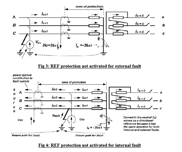
In above figure, wye-wye-delta connected transformer the differential protection is meant to be operated for Y-Y winding. The star point of bushing CTs as shown is pointed towards transformer winding which is very important because star point directed towards opposite of winding may lead to out of the zone protection and transformer may operate due to external fault which is not the objective of differential protection. If bushing CT star point is made towards transformer winding then residual current (Ires) 3Io cancels neutral current (In) whereas otherwise 3Io and In became approximately in phase for internal ground fault leading to trip the transformer in internal fault only. Refer to Figure 3 and Figure 4 for better illustration.
Now, let us consider the Restricted Earth Fault Protection (REF, 87N) occurrence in power transformer and factor responsible for tripping of transformer in REF. REF is considered in this blog since it is often less prioritized which may hamper the transformer in long run since occurrence of this type of fault is due to the internal problem. The analysis of REF fault in this blog is considered such that low impedance differential protection is adopted in power transformer since majority of power transformer installed by Nepal Electricity Authority has adopted this protection philosophy.
Tripping Logic for REF protection
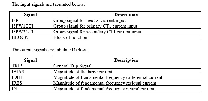
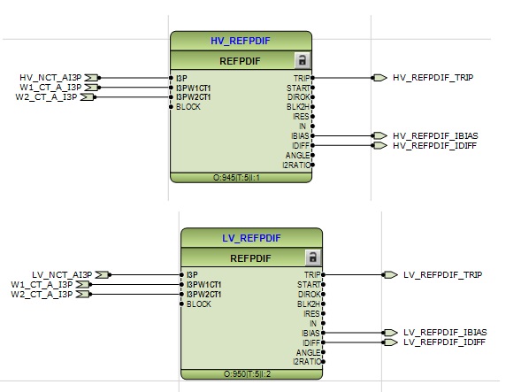
The power transformer considered under this blog in Y-Y connected thus REF protection must be adopted for both HV and LV winding, the logic of which has been given below. The tripping logic could be customized according to your protection requirement but we must be sure that it ensures the healthy protection system.
Fig 5: Tripping Logic for REF protection

There is different tripping logic for each individual protection which could be observed in Application Configuration in PCM 600 for each relay and could be customized according to requirement.
Fault Analysis using COMTRADE
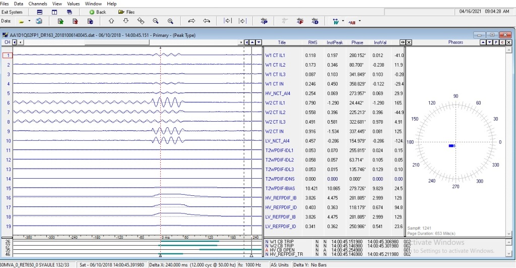
The oscillatory waveform and phasor diagram of downloaded DR could be analyzed from other software capable of opening such files such as Wave win. Let us open one DR obtained due to tripping of power transformer in REF to have the basic understanding of DR for fault analysis.
Fig 6: Comtrade file view of HVREF fault in transformer
The above DR is of power transformer tripping in HVREF fault. The red dotted vertical line indicates the waveform at instant of fault whereas black dotted vertical line could be scrolled ac per our requirement to see the waveform details and values at any instant. The fault magnitude or magnitude at any instant could be read from right window beside waveform. The phasor diagram of each channel could be observed in right most window. We could observe during the occurrence of fault the waveform is abnormal. Since we are concerned with REF protection, we need to concentrate on the particular channel signal responsible for tripping of particular protection. The input and output signal for particular protection could be known from tripping logic and for better analysis only those signals could be analyzed by omitting the unwanted signal waveform for better analysis. For REF protection let us concentrate on the channel responsible as indicated in tripping logic. The transformer considered in this case in 132/3kV, 30MVA where full load current on HV and LV side is 131.21 A and 524.87 A respectively. The REF protection is set as 10% of full load current such that current exceeding 13.12A on HV and 52.48A on LV side trips TRAFO in HVREF and LVREF respectively.

In above figure all other irrelevant channel waveforms are omitted for better view of selected waveform. We could observe prior to fault all waveform is in normal shape with normal magnitude according to load current but at instant of fault waveform became abnormal. We could see fault was triggered from R phase HV bushing CT where its RMS value recorded was 31.90A whereas RMS current of Y and B phase was 10.22A and 9.50A respectively. This abnormality in R phase of HV leads to magnitude of neutral bushing CT of HV as 22.71A leading to differential current of 66.68A tripping the TRAFO in HVREF since it exceeds the set value of 13.12 A. It gives a better indication that fault was triggered from R phase thus post fault we must concentrate on the reasons why R phase triggers the fault. The reason might be due to wiring mismatch of CT core of that particular bushing, incorrect star point leading to maloperation of relays or in extreme cases it might due to failure of R phase winding on HV side. Particularly, in this case there was maloperation of relay due to wiring mismatch leading to incorrect star point on HV side.
Another way to see the healthiness of protection without any software is to scrolling the keys of relay and observe the display. For REF protection, go to differential function status of relay and enter the REF mode. There are several readings displayed there in real time such as Idiff, Ibias, Ires, In etc. If during the normal operation Ires and In are subtractive then your protection is healthy since during the fault only Ires and In becomes additive. If Ires and In are additive during normal operation then you must trace out the wiring from bushing CT to TRAFO Marshalling Box to Relay Panel TBs to Relay TB to sort out the issue.
I hope this blog to some extent helps about the protection features and basics of fault analysis but extensive analysis depends upon your interest and alignment with use of software and also with input and output signals responsible for particular protection adopted. I shall be discussing about the faults in transmission line and its analysis in next blog.


