Transmission Line is one of the major components of electrical power system; commonly it can be related with highway of electrical energy from where energy is transferred from source to load. Since, overhead transmission line are directly exposed with outer atmosphere and it passes through different land profile with varying climate, protection of transmission line is one of the major concern for power system operators. The failure of transmission line may lead to system instability ultimately resulting in system collapse, which is often seen and observed as headache for operators. In this blog, I will be discussing about the basics of transmission line protection and relay setting parameters required for protection of transmission line.
The protection of transmission line is broadly classified in two categories which are further classified according to protection requirements required by utility considering the sensitivity of transmission lines:
1) Main Protection
The main protection of transmission line is achieved by distance protection generally referred as 21 in device numbering. Distance relaying are considered since overcurrent relaying is too slow or is not selective. Distance relays are preferred to overcurrent reIays because they are not nearly so much affected by changes in short-circuit-current magnitude as overcurrent relays are, and, hence, are much less affected by changes in generating capacity and in system configuration.
2) Backup Protection
Directional overcurrent and earth fault are generally referred as backup protection referred as 67/67N in device numbering.
The protection of transmission line is done at substation where the particular lines are terminating. We have read lot about theory in books thus I am jumping directly towards the content starting with figure given below:
Figure 1 represents the single line diagram adopted for transmission line protection at double bus substation where LINE 1 is terminated. The protection associated with LINE 1 shall be employed at substation represented with double bus in given figure. Since we are only concerned with protection of transmission line, only short introduction regarding other protection shown in single line diagram will be given.
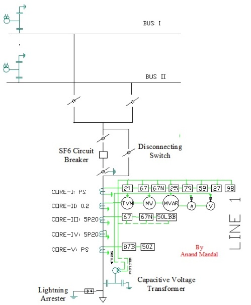
Figure 1: SLD of transmission line protection
It is very well known to us that input to relay for desired protection is given by CT which generally serves two purposes: metering and protection. Here, metering core is designated as core 2 with accuracy class of 0.2. Core 1, Core 3, Core 4 and Core 5 serves the purpose for protection where Core 1 is used as main protection, i.e. distance protection (21) whereas Core 3 serves for backup protection and Core 5 is employed as busbar differential protection. It’s better to employ PS accuracy class CT for protection since there are no issues regarding CT saturation.
According to basic protection philosophy, core towards bus shall be used for line protection and core towards line shall be used for bus protection to cover the entire protection zone between CT cores.
Setting Parameters for Main Protection (Distance Relay, 21)
- General Parameters
Before getting started with setting parameters, first of all required data needs to be gathered and accessed, calculated and then finally to be written in relay for proper functioning of desired protection. Figure 2 represents the general information regarding parameters at Substation A. The line considered in this blog is of 132 kV voltage level, however voltage level does not affects the setting procedures. Process is same for 220 kV, 400 kV, 765 kV and 1200 kV lines.
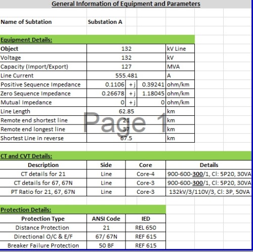
Figure 2: General Information of Parameters
The only complicated thing to be calculated is positive and zero sequence impedance of line which is major input for operation of distance relay. The properties of conductor, OPGW/earth wire and tower configuration is required for computation of sequence impedances. It can be calculated manually or with the help of software like MATLAB, Power World Simulator etc. or with impedance measurement equipment. Generally, I prefer to use Simulink of MATLAB with tool ‘Compute RLC line parameters’ for computation of sequence impedance. The graphical interpretation of protected line and adjoining line are shown in Figure 3.
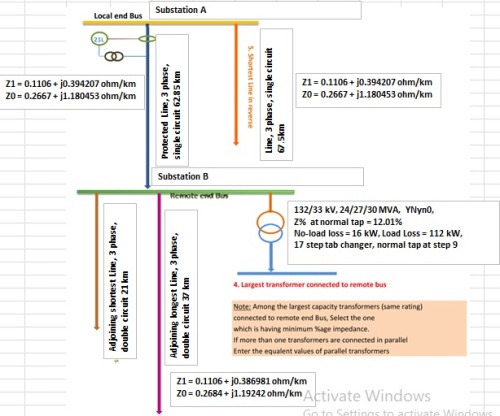
Figure 3: Graphical Interpretation of protected line
2) Parameters for Line Protection
After done with the general parameters we need to calculate the positive sequence, zero sequence and mutual impedance of overall line length of protected line and every adjoining lines which has been shown in figure 4. Since, we are concerned with protection of single circuit line there is no zero sequence mutual impedance, only positive and zero sequence impedance are presented.
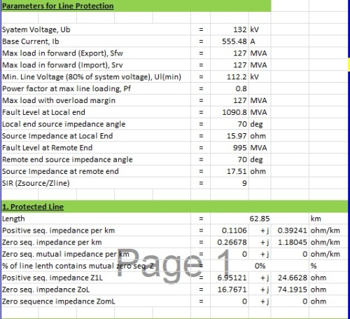
Figure 4: Parameters for protected line
Similarly, the parameters for line in reverse from local end and adjoining line from remote end are calculated in same way which has been given in figure 5.
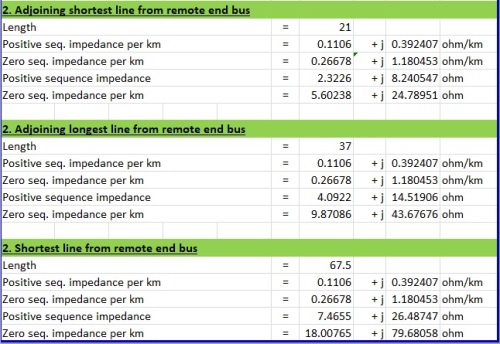
Figure 5: Parameters for adjoining lines
3) Zone Reach Settings
The features of distance relay is that line is protected by dividing the line into different zones considering its length as well as length of adjoining lines from local and remote end. Generally, distance relay functions by separating into five (5) zones referred as zone 1, zone 2, zone 3, zone 4 and zone 5. The zone 4 and zone 5 are known as reverse zone whereas former three zones operate in forward region. The zone reach setting may vary according to grid code or standards of utility or country, but here I will be showing general setting criteria for respective zones as given below:
Zone 1: 80-85 % of protected line
Zone 2: 120 % of protected line
Zone 3: 120 % of protected line + 120 % of longest line from remote end
Zone 4: 20% of protected length
Zone 5: not required here
The zone reach setting for distance relay alongwith operating time for respective zones has been shown in figure 6. The operating time may be adjusted as according to requirements or standards set by regulator/utility/country.
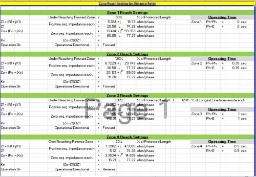
Figure 6: Zone Reach Setting for Distance Relay
After calculating the zone reach setting, you need to input this data into relay in their format which may be different for every manufacturer like ABB, GE, Alstom, CG etc. because parameter name adopted by manufacturer is different, however the procedure is same. For that you need to read the relay manual and input this data as described.
Setting Parameters for Backup Protection
- Directional O/C and E/F, 67/67N
Before getting started with settings for directional overcurrent and earth fault relay, let us review the operating time of different categories of IDMT relay. Generally there are three types of IDMT relay having Standard (Normally) Inverse, Extremely Inverse and Very Inverse characteristics which have different operating time.
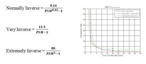
Figure 7: IDMT Relay characteristics
Since, we are using normally inverse relay for this purpose, we have adopted this relay characteristics for calculation of operating time.
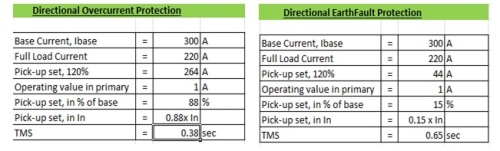
Figure 8: 67, 67N Setting Parameters
Base Current means the tapped CT ratio at primary whereas full load current means the maximum load current expected to be carried by line. The pick-up setting for overcurrent is generally set as 110% or 120% whereas for earth fault it is set as 10% or 20% of full load current.
2) Breaker Failure Protection (50BF)
Pick – up set same as earth fault protection, i.e, 0.15 x In. The breaker failure protection is set with 2 stages, one for re-trip and the other back- up trip.
The time delay is adopted based on the calculation below.
Re – Trip Time Delay (minimum) = Relay Reset Delay + CB Opening Time Delay + Margin
= 20 + 40 + 20
= 80 ms
Re – Trip Time Delay (Set) = 100 ms
Back- Up – Trip Time Delay
(minimum) = Re – Trip Time Delay + Relay Reset Delay + CB Opening
Time Delay + Margin
= 100 + 15 + 40 + 20
= 175 ms
Back – Up – Trip Delay (Set) = 200 ms
Beside this, there are various other auxiliary protection features provided by manufacturer for line protection such as broken conductor detection, power swings, fault locator etc. the setting of which are also derived from the parameters calculated above.
Hope you have enjoyed this blog. If there are any queries regarding the content of the blog, please feel free to write me at
-Anand Mandal (anandkalyaneee@gmail.com)

